
Designing enclosures from flat panels
An enclosure from the laser consists of flat panels. The real work is not in the cutting but in the question of which dimension depends on which.
Reviewed on 31 August 2026
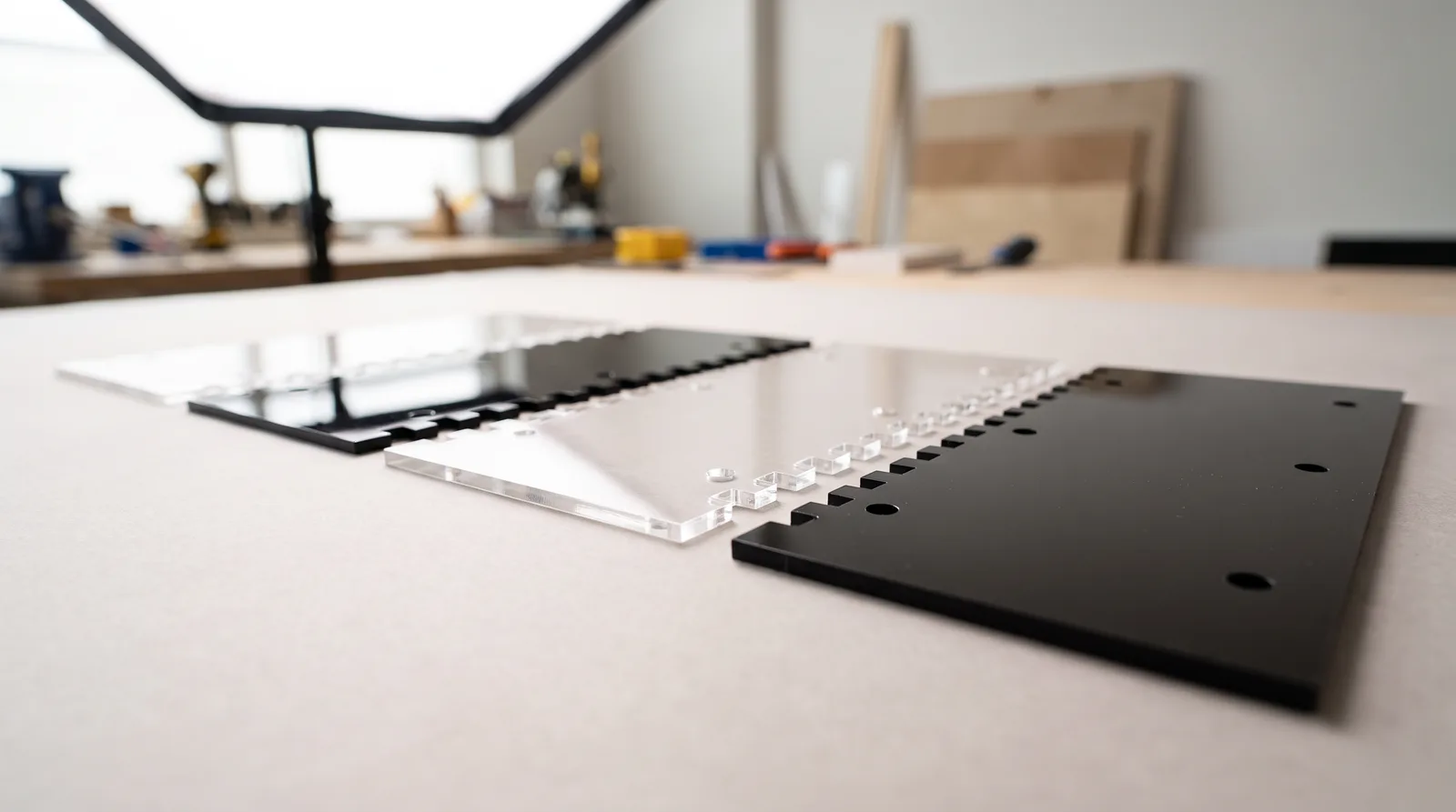 AI-generated
A rectangular enclosure has six faces but rarely six different parts: base and lid are usually identical, so are the two sides, and only front and back differ through their cut-outs. Six faces thus become three or four drawings — that is the first step, and it saves more time than any optimisation afterwards.
All parts lie flat on the same sheet. What stands upright in the finished enclosure is one surface beside another when you draw it. This translation between the three-dimensional object and the flat drawing is the actual design step.
Internal or external dimension — decide that first
Before you enter any dimension: is the internal or the external size fixed? You cannot have both. If a circuit board, a display or a power supply has to fit inside, the internal dimension is given and the external one follows. If the enclosure has to fit into a rack or onto an existing footprint, it is the other way round.
The most common design error is switching from one way of thinking to the other halfway through the drawing. Then exactly one material thickness is missing at the end — with 3 mm acrylic the board jams, with 5 mm it no longer fits at all.
Dimension chain with a fixed internal size
| Dimension | Calculation | Example with 3 mm material |
|---|---|---|
| Internal width | required | 100 mm |
| External width | internal width + 2 × material thickness | 106 mm |
| Width of base and lid | equal to the external width | 106 mm |
| Width of front and back | internal width, if they sit between the sides | 100 mm |
| Height of the side panels | internal height + 2 × material thickness | internal height + 6 mm |
Which wall sits outside and which fits between them is decided once for the whole enclosure — otherwise the chain no longer works out at one corner.
Finger joints: the joint that aligns itself
The most widespread corner joint for panel enclosures is the box joint, usually called finger joints: alternating tabs and recesses along the edge that interlock. It has three advantages — it aligns the parts by itself during assembly, it considerably increases the glued area, and it holds together even without adhesive.
Two to three times the material thickness has proven a good finger width: with 3 mm material, roughly 6 to 9 mm. Narrower fingers look more delicate but break out more easily, especially in brittle acrylic. It is also important that each edge begins and ends with a tab — otherwise a thin tongue of material stands at the corner and snaps off the first time you assemble it.
The finger depth always corresponds exactly to the material thickness of the opposing wall. If it is smaller, the tab does not sit flush; if it is larger, it protrudes and has to be reworked.
Material thickness is not as exact as it sounds
Here lurks the error that defeats the cleanest dimension chain: “3 mm acrylic” does not mean the sheet is 3.00 mm thick. Cast acrylic is manufactured with a considerable thickness tolerance — ± (0.4 + 0.1 × thickness) mm is permissible. At 3 mm that is up to ±0.7 mm; the sheet may therefore lie anywhere between 2.3 and 3.7 mm.
Anyone drawing a groove or a finger recess at exactly 3.0 mm will therefore get, depending on the batch, a joint that jams or one that rattles — from an identical file. That is not a manufacturing fault but the material standard.
Three ways to deal with it: measure the actual thickness of your sheet and draw accordingly. Or design joints that tolerate variation — screwed rather than slotted, or with an adhesive gap. Or use precision cast acrylic, manufactured to ±0.1 mm; for fits that genuinely have to be right, that is the most direct route.
The tolerance chain
Every slotted joint brings play with it. With tab and slot it is twice the kerf — around 0.7 mm with 3 mm acrylic. Across four corners that adds up to an enclosure that visibly sits askew, even though every individual part is correct.
So either you compensate for the kerf in the drawing, or you plan for adhesive that fills the play. Both together is the most robust. How the compensation works arithmetically is covered in the article on kerf.
How does the lid come off again
An enclosure finger-jointed and glued all round is stable but final. For anything containing electronics you need access. Three approaches have proven themselves: the lid is screwed down, in which case you need threaded inserts or glued-on strips with holes — acrylic itself does not hold a cut thread. Or the lid is inset and rests on strips running round the inside. Or the enclosure is held together by threaded rods passing through all the panels; you often see this construction in amplifiers and power supplies.
In every case: fixing points belong in the drawing before the fingers are distributed. Retrofitting a hole rarely puts it where material is still left.
Cut-outs for connectors
Sockets, switches and displays almost always sit in the front or back panel. Take the dimensions from the component data sheet, not from a caliper on a sample — and remember that a cut-out comes out larger than drawn because of the kerf. With round sockets that is welcome clearance; on a display window it is visibly annoying.
Ventilation slots are cheaper than any other form of cooling, but they cost cutting length and therefore money. A few longer slots are cheaper than many short ones for the same open area.
How to proceed
- Fix the internal dimension — what has to go inside, with how much clearance.
- Decide which walls sit outside and which fit between them.
- Work through the dimension chain once completely and note the external sizes.
- Distribute the fingers, with a tab at both ends of every edge.
- Enter cut-outs, holes and fixing points.
- Compensate for the kerf and order a single pair of corners as a test cut before the whole enclosure runs.
Generators as a starting point
For standard shapes you do not have to draw anything by hand. Free generators such as boxes.py produce finger-jointed boxes including cut-outs as a ready vector file, with an adjustable kerf setting. We have been pointing customers to them for years when they ask for a starting point.
Two things nevertheless remain your job: the generator’s kerf value has to match our material — there is a dedicated test-cut generator for that. And you enter the cut-outs for your specific components yourself afterwards.
Frequently asked questions
- How wide should the finger joints be?
- Two to three times the material thickness, so 6 to 9 mm with 3 mm material. Every edge begins and ends with a tab, otherwise the thin corner breaks out.
- Do I specify the internal or the external dimension?
- You fix one of the two and the other follows. For an electronics enclosure it is almost always the internal one; the external width is then the internal width plus twice the material thickness.
- Does a slotted acrylic enclosure hold without adhesive?
- For a mock-up yes, permanently only to a limited extent — the play from the kerf means the joint does not sit tight. For an enclosure that will be used, we recommend gluing or screwing.
- What material thickness for an enclosure?
- For enclosures up to about shoebox size, 3 mm is the standard — almost half of all parts we produce have that thickness. From roughly 200 mm of unsupported span, or under load, 5 mm is the safer choice.
- Is a 3 mm sheet really 3 mm thick?
- Not necessarily. Cast acrylic permits a thickness tolerance of ± (0.4 + 0.1 × thickness) mm — up to ±0.7 mm at 3 mm. For dimensionally critical grooves and fingers, measure the sheet or use precision cast acrylic at ±0.1 mm.
Read on
Sources
- Our own production: tab-jointed and instrument enclosures, Raspberry Pi cases, clock and guitar bodies, 2019–2026
- Order analysis from 2019: 427 customer profiles relating to enclosures, front panels or tab parts