
Allowing for kerf
The laser removes material. If you ignore that in your drawing, you get parts that are individually correct and still do not fit together.
Reviewed on 30 August 2026
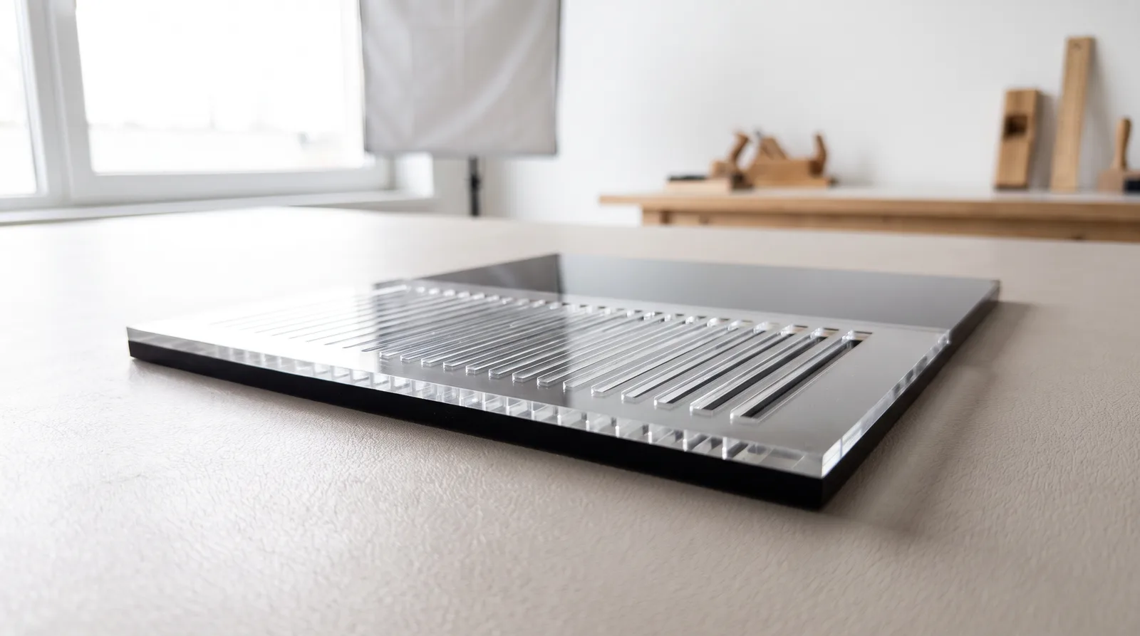 AI-generated
A laser beam is not a mathematical line but a tool with width. It travels along the centre of the line you drew and vaporises half of its width to either side. This loss of material is called the kerf.
The machine does not compensate for it. It cuts exactly where your line is — there is no tool radius compensation as in milling. That is not a shortcoming but the precondition for you deciding which side of the line the material disappears from.
What this means for your dimensions
| Drawn | Cut | Correction in the drawing |
|---|---|---|
| Disc Ø 20 mm | Ø 20 mm − 1 kerf | add the kerf |
| Hole Ø 20 mm | Ø 20 mm + 1 kerf | subtract the kerf |
| Outer edge of a panel | narrower than drawn | add the kerf |
| Cut-out, slot, bore | larger than drawn | subtract the kerf |
Always a full kerf, not half of it: the loss occurs at both opposing edges and adds up across the dimension.
Why tab joints are affected twice
In a tab-and-slot joint the effect works twice in the same direction. The tab becomes one kerf narrower, the matching slot one kerf wider. The play between them is therefore twice the kerf.
Concretely: with 3 mm acrylic and a kerf of around 0.35 mm, a tab drawn to nominal size sits in its slot with roughly 0.7 mm of play. That is the difference between a joint that grips and one that falls apart — and the most common reason a carefully designed enclosure does not hold.
You can compensate in one place or spread it out: draw the tab one kerf wider, or the slot one kerf narrower, or each by half. Mathematically it is equivalent. In practice it is usually easier to adjust the internal dimension, because outer contours often depend on other measurements.
How wide is the kerf
There is no universally valid figure. The kerf depends on the material and its thickness, on the focal length of the lens, on the pressure of the process air and on the manufacturing tolerance of the sheet itself. It can even vary within the same batch.
The following values are figures from our own production. They serve as a starting point for design — they do not replace a test cut.
Reference values from our production
| Material | Thickness | Kerf |
|---|---|---|
| Acrylic | 3 mm | 0.3–0.4 mm |
| Birch plywood | 3 mm | 0.2 mm |
Reference values, not a guarantee: a different lens or a deviating batch shifts the figure. For dimensionally critical fits, the test cut decides.
The comb shows where the limit lies
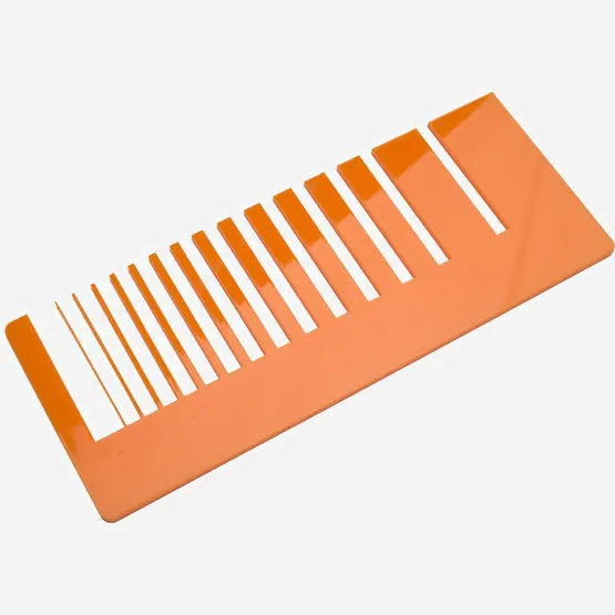
Cast acrylic — on the left, at 0.5 mm, barely any substance is left of the web. 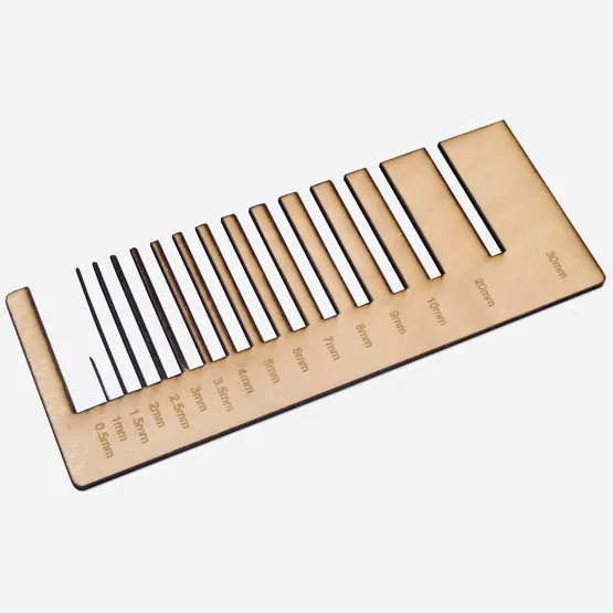
Birch plywood — identical drawing, visibly more material left at the fine steps.
We cut this pattern on every material in our range. The engraved scale runs from 30 mm down to 0.5 mm.
The comb is the kerf made tangible. From right to left, slots and webs become ever narrower — 30, 20, 10, 9, 8 mm and on down to 0.5 mm. At the wide steps the loss of material goes unnoticed. At the narrow ones it decides whether anything remains at all.
The reason is the same as above: a web is cut from two sides and therefore loses a full kerf in width. Of a web drawn at 0.5 mm, acrylic with a kerf of 0.3 to 0.4 mm leaves only about 0.1 to 0.2 mm — a thread that breaks or distorts when the part is removed. That is exactly what you see at the leftmost step in the photo.
Because plywood has a smaller kerf, the same drawing leaves more material standing there. Two combs cut from an identical file therefore look different at the fine steps — that is not a fault but the difference between materials.
Two problems with the same cause
Delicate grilles, louvres and lettering with thin connections do not fail because of the laser but because of this arithmetic. If a letter such as an “e” hangs together on a bridge only 0.4 mm wide, that bridge is gone after cutting and the inner part falls out.
The same applies in reverse to very narrow slots: they end up wider than drawn. A slot drawn at 0.5 mm, intended to take a 0.5 mm sheet, will sit with noticeable play afterwards — in reality it measures more like 0.8 to 0.9 mm.
When you can ignore the kerf
For decorative parts, signs, tags and anything that stands on its own, a tenth of a millimetre is irrelevant. Do not convert anything here — you only make the drawing harder to read.
You do need to account for the kerf wherever two cut parts interact: tab joints, enclosures, fits for shafts and bearings, meshing gears, inlays, front-panel cut-outs for sockets and displays.
The test cut
- Draw a narrow strip with three slots: one at nominal size, one half a kerf narrower, one a full kerf narrower.
- Add a matching tab at nominal size, several times over.
- Order both on the smallest sheet format — it costs little and settles the question for good.
- Use the combination that joins under light pressure and does not fall out by itself. Note that correction value for the material and thickness.
This route is more common among our customers than you might think: a considerable share of repeat orders begins with a small test sheet before the actual production run. That is not fussiness but the cheapest way to avoid an expensive faulty batch.
Frequently asked questions
- Does the laser subtract the kerf automatically?
- No. We cut along the centre of the drawn line, without tool compensation. The correction belongs in your drawing — that way you keep control over which dimension ends up exact.
- Do I allow half a kerf or a full one?
- For a dimension bounded by two cut edges — width, diameter, slot length — a full one. Only if you align a single edge against a fixed reference face is it half.
- Why do my tab joints wobble despite an exact drawing?
- Because the effect adds up across tab and slot: the tab becomes one kerf narrower, the slot one kerf wider. The play is therefore twice the kerf — around 0.7 mm with 3 mm acrylic.
- How wide is the kerf in 3 mm acrylic?
- As a starting point we work with 0.3 to 0.4 mm. The figure varies with lens, process air and batch; for dimensionally critical fits we recommend a test cut.
- How thin can a web be?
- Below 1 mm it becomes unreliable. A web drawn at 0.5 mm loses a full kerf in acrylic and retains only around 0.1 to 0.2 mm — it breaks when the part is removed. Our comb samples show this for every material down to 0.5 mm.
Read on
Sources
- Customer correspondence and test cuts from our own workshop, 2019–2026
- Formulor artwork conventions, formulor.de/help/classic.html